The digital sector experiences a major transformation. Artificial intelligence, 5G, and cloud computing need massive bandwidth. Traditional copper wiring faces clear limits from electrical resistance and signal loss. These issues block wider progress. The industry shifts to photonics to handle such challenges. Yet, allowing electronic devices to employ optical fibers for long-distance data transfer involves more than cable swaps. It centers on a complex conversion process at the network core. This guide explains methods to link electrons and photons. Such steps create fast, extended infrastructure.
What is the Core Component for Electro-Optical Conversion?
Electronic devices rely on binary electrons for signals. Optical fibers carry data through light pulses. A specialized translator enables interaction between these systems. This part handles 400Gbps or 800Gbps rates with speed. It also fits compactly in standard rack switches.
The Optical Transceiver Module
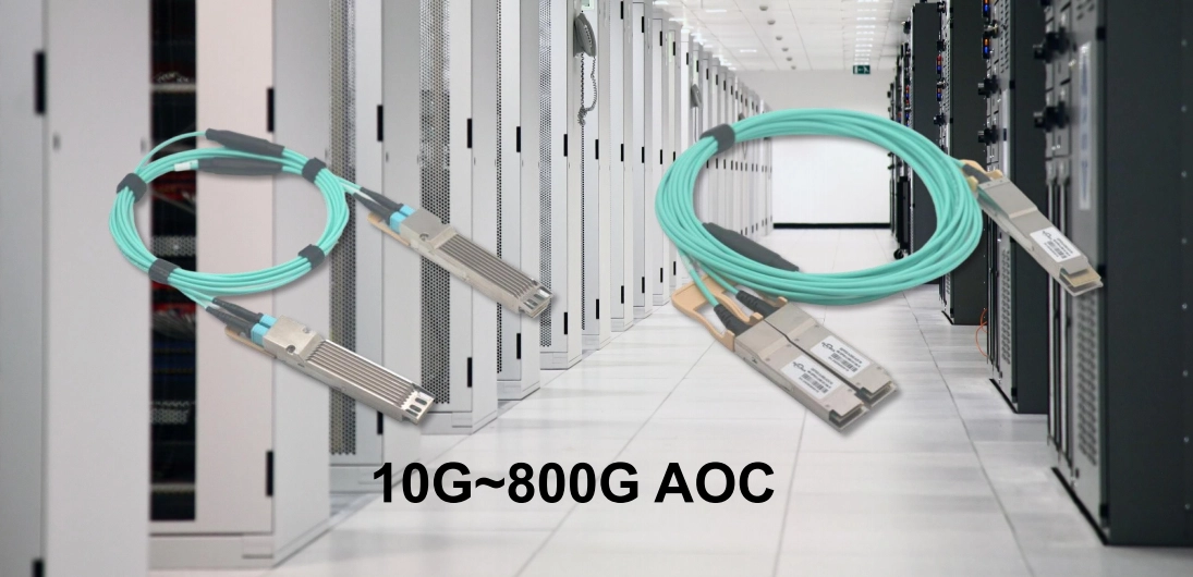
The optical transceiver appears as a key part in this setup. It consists of pluggable hardware for SFP, QSFP28, or QSFP-DD ports in network devices. This module acts as the main physical link. Electrical signals from the device board connect to network optical fibers there. As a result, it supports seamless data flow.
TOSA and ROSA Assemblies
The Transmitter Optical Sub-Assembly (TOSA) and Receiver Optical Sub-Assembly (ROSA) perform main tasks inside the transceiver. TOSA changes electrical input to light signals with a laser diode. Meanwhile, ROSA applies a photodetector to shift incoming light to electrical current. These units ensure reliable signal changes over distances.
Driver and TIA Circuitry
Exact control defines success in fast links. The Driver IC oversees laser power and modulation. It makes light pulses sharp and clear. At the receiver, a Trans-Impedance Amplifier (TIA) raises the small current from ROSA to useful voltage levels. Thus, it upholds signal quality after light travels many kilometers.
How Do Optical Chips Power Long-Distance Transmission?
The optical chip serves as the core in each transceiver. Long-distance communication covers ranges from 2km to 80km. These setups demand distinct chip features. They differ sharply from short-range uses in one space.
High-Performance Laser Diodes
VCSEL lasers suit short distances well. For long-distance data transfer, Distributed Feedback (DFB) or Electro-absorption Modulated Lasers (EML) prove essential. These chips generate a tighter light spectrum. Such output cuts chromatic dispersion. This effect occurs when light colors move at different speeds and distort signals over far reaches.
Precision Packaging Requirements
The Butterfly package helps sustain performance in high-end chips during laser sub-assembly production. Long-distance lasers create considerable heat. They also demand firm wavelength control. The package holds a Thermoelectric Cooler (TEC) effectively. Therefore, it keeps the 1550nm signal steady at 1550nm. External conditions do not affect this stability.
Spectral Width and Dispersion
Light pulse clarity limits data push over 40km or 80km. Advanced optical chips reduce spectral width. This feature preserves high data speeds. Signals remain legible at the fiber’s distant end as a result.
Which Fiber Infrastructure is Required for Long-Range Connectivity?
Linking devices across long spans needs strong chips and more. It calls for solid grasp of the fiber medium. Selecting the incorrect fiber type causes full link breakdowns. Transceiver power alone cannot prevent this.
Single-mode vs. Multi-mode Fiber
Single-mode fiber (SMF) fits long-distance needs. Multi-mode fiber has a broad core. Light bounces inside it, leading to modal dispersion. Single-mode fiber uses a small 9-micron core instead. Light follows a direct path there. This design allows distances far beyond multi-mode limits.
Attenuation and Power Budget
Fiber takes in light bit by bit each kilometer. Link power budget involves matching transceiver output to receiver sensitivity. In the Communications Industry, optical chips supply key launch power. Proper levels mean stable connections. Without them, packet loss persists.
Advanced Cooling for High-Power Links
Transceivers for 400G and 800G over long distances draw higher power. They produce added heat as well. Leading makers offer liquid-cooling modules as solutions. These keep internal parts below thermal thresholds. Continuous high-load runs stay safe this way.
Why Choose an IDM Partner Like DEEPETCH for Your Fiber Strategy?
Data center or telecom network builds avoid untested components. Partner choice shapes key decisions. DEEPETCH excels in photonics. It follows an IDM (Integrated Device Manufacturer) model. Fabless firms design chips and hand off the rest. DEEPETCH controls the full path. This includes design, wafer fabrication, testing, and packaging.
Vertical integration yields practical reliability. The company started in 2019. It grew to make 400G and 800G modules for AI advances. More than 1,560 clients worldwide rely on these. Selecting their products goes beyond chips. It accesses a supply chain with vast Chips in Stock reserves. Projects dodge lead-time delays through this.
Vertical Integration and Customization
The IDM model fosters tight chip-housing links. No other setup matches this. Electrical drivers adjust to laser chip impedance precisely. Lower power use follows. Signal clarity rises for long links too. Overall system gains benefit from these ties.
Proven Reliability and Certifications
Key networks value reliability above all. DEEPETCH meets global standards such as IATF 16949 and ISO 9001. The Company Overview outlines this focus: Modules endure strict stress tests before rack use and confidence in steady operation comes from such measures.
Future Trends in Fiber Optic Communication Technology?
Progress surpasses 800G toward 1.6T and further. Electronic devices will integrate optical fibers more deeply. Efficiency will improve steadily as well.
Co-Packaged Optics (CPO)
The optical translator shifts from pluggable form to direct build on processor bases. Co-Packaged Optics lowers signal loss further. It cuts power draw too. Ultra-long-distance links gain sustainability this way. Network futures align with these changes.
Intelligent Optical Monitoring
Modules will convert signals and track fiber status in real time. Diagnostic sensors fit into optical chip packaging. Networks adjust power or reroute traffic on their own. Actions occur before fiber issues arise. Proactive care strengthens links.
FAQ
Q1: Can I use fiber optics with a standard RJ45 Ethernet port?
A: A standard RJ45 port suits copper cables. Fiber needs a switch with SFP/QSFP slots plus a fitting optical transceiver. A separate media converter works as an option.
Q2: What is the maximum distance for fiber optic communication?
A: Standard long-haul transceivers span up to 80km. Optical amplifiers and coherent technology push fiber links to thousands of kilometers. Ocean routes benefit from this reach.
Q3: Why are 800G modules becoming the standard for AI?
A: AI models handle huge data volumes across thousands of GPUs at once. 800G modules deliver required density and pace. They stop networks from bottlenecking AI training.
Q4: Is liquid cooling necessary for optical transceivers?
A: Liquid cooling rises in use for dense 400G and 800G setups. It handles heat from quick optoelectronic parts better. Traditional air cooling falls short in comparison.
Q5: How do I contact a specialist for custom fiber solutions?
A: Tailored guidance on high-speed optical modules and chip sourcing comes from technical experts. Reach them via the Contact Us page at DEEPETCH.