
A ceramic tube shell sits between the laser chip and the outside world: it holds the optical window in line with the die, carries the heat the die makes, and keeps the package sealed against moisture and particles. That makes the tube one of the highest-leverage parts in a laser diode or optical package, and one of the most underspecified in a first RFQ.
This article covers the three specification decisions in order: which ceramic material the heat path requires, which tolerances the optical and sealing faces need, and how the sealing method changes the tube’s requirements. It assumes a standard LD or optical subassembly on a metalized submount, but the same structure applies to higher-power bar packages with different current margins.

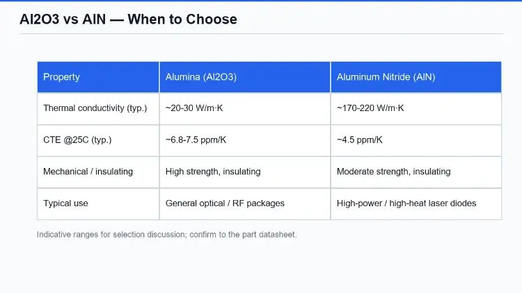
Most production ceramic tube shells are alumina (Al2O3). It is strong, insulating, chemically stable, and inexpensive, and its thermal conductivity of roughly 20-30 W/m·K is adequate while the die carries a few watts. Aluminum nitride (AlN), with thermal conductivity in the 170-220 W/m·K range, moves heat an order of magnitude faster, and that is the only reason to pay more for it: the tube becomes the heat path when the die runs at high current or high junction temperature.
The decision is therefore driven by the device’s rating, not by habit. A typical 1.3 um CW device at a few hundred milliwatts of optical output often stays comfortably on alumina; a high-power bar or a package with no external heatsink margin may not. Two secondary checks belong in the decision: the CTE match between ceramic, submount and die (AlN is closer to InP and GaAs than alumina is), and the window alignment budget, since the tube’s bore geometry is what keeps the optical axis stable over temperature. If the rest of your platform is alumina-based, the DEEPETCH product pages for the Alumina Ceramic Substrate and for Aluminum Nitride (AlN) show the two material families as specified parts rather than custom-only options.
A tube shell is only as good as the four features the assembly depends on. Bore diameter and tolerance set how the die and submount seat, and how the tube slides over the leadframe. Bore concentricity sets how close the optical axis of the window end is to the bore axis, and it is the number that shows up in your beam pointing after assembly. Seal-face flatness determines whether the braze or glass-fusion joint is uniform around the circumference. Step height at the end face works together with the cap tolerance to set the braze gap, and a braze gap that is too wide or too narrow fails in different ways.
| Feature | What it governs | Specification note |
| Bore diameter + tolerance | Die and submount seating, leadframe clearance | Give diameter and tolerance; state fit intent (slide / press) |
| Bore concentricity | Optical axis alignment, beam pointing | Specify as position of bore axis to end-face datum |
| Seal-face flatness | Uniform braze / glass-fusion joint | Flatness per end face; note which face seals |
| End-face step height | Braze gap with the end cap | Specify with the cap tolerance as a pair |
The step is the feature people miss. The braze gap is set by the tube step plus the cap step, so a cap tolerance quoted on its own means nothing without the matching tube tolerance. Specify the joint as a pair, and state the target gap or the sealing method, because the two imply different step limits.
Sealing method is set by the application, not by preference. Glass-to-ceramic fusion is the classic choice where the window itself must be part of the seal, and it pairs naturally with a laser diode window stack. Metalized ceramic with a braze (AgCu or AuSn families) is the workhorse for hermetic LD and detector packages, and it is the path when the tube, cap and submount are all metallized for the same chemistry. For non-hermetic or low-power optical subassemblies, an epoxy pot may be the intended end state, and the tube then needs a different surface finish and a different flatness budget.
Whichever method you choose, write the leak requirement down. A hermetic specification needs a leak-rate limit, an acceptance test (helium mass-spectrometer or bubble test), and the environment the package must survive. ‘Gas tight’ without a limit and a method is not a specification, and it is the single most common gap in a first tube RFQ. If the device side of the package is evolving, the DEEPETCH DE-CW-1310 DFB epi wafer page is a reference point for the wafer products that go into the packages you are specifying; and when the question is why the platform is moving to higher data rates in the first place, the 1.6T vs 800G transceiver article covers the system pressure that is driving package power budgets up.
A tube, a cap and a submount are specified as one joint system. If the ceramic tube is the first item on your BOM, write the RFQ so the supplier can price the fit: die type and submount style, ceramic material and grade, bore and seal-face tolerances, step height with the cap, sealing method and leak-rate target, finish on the window end, lifetime and environment, quantity, and inspection plan. Mark the fields you have not decided, because ‘TBD on the seal’ and ‘seal method fixed’ are different pricing problems.
DEEPETCH carries ceramic packaging products from the Butterfly package form to ceramic CBGA and multilayer carriers, alongside the alumina and AlN material lines. Send DEEPETCH the die type, the thermal budget and the sealing method with the open items marked, and the tube specification you get back is one you can hold the part to.
A No. AlN costs more, and its mechanical margin is different from alumina’s. If the device’s heat can be carried by alumina at your current rating, the extra thermal conductivity buys you nothing you can use. Choose AlN when the heat path is through the tube and the current or junction-temperature margin is the constraint.
Tight enough for the fit, not tighter. A press-fit bore needs a tighter band than a slide fit, and the concentricity number should follow your beam-pointing budget after assembly. If you cannot state the pointing budget, state the application and the assembly method instead, and let the ceramic side propose the pair.
Sometimes, but the flatness and step budgets differ. A non-hermetic pot does not need the seal face the braze joint does. Specifying the hermetic tolerances on both keeps one part number alive if the design later moves to hermetic, at the cost of a slightly higher tube price.
Die type and orientation, thermal budget, material and grade, bore and concentricity, seal-face flatness, step height with the cap, sealing method and leak-rate target, cap material, test method, lifetime and temperature range, quantity, and inspection plan. Mark every open item explicitly.
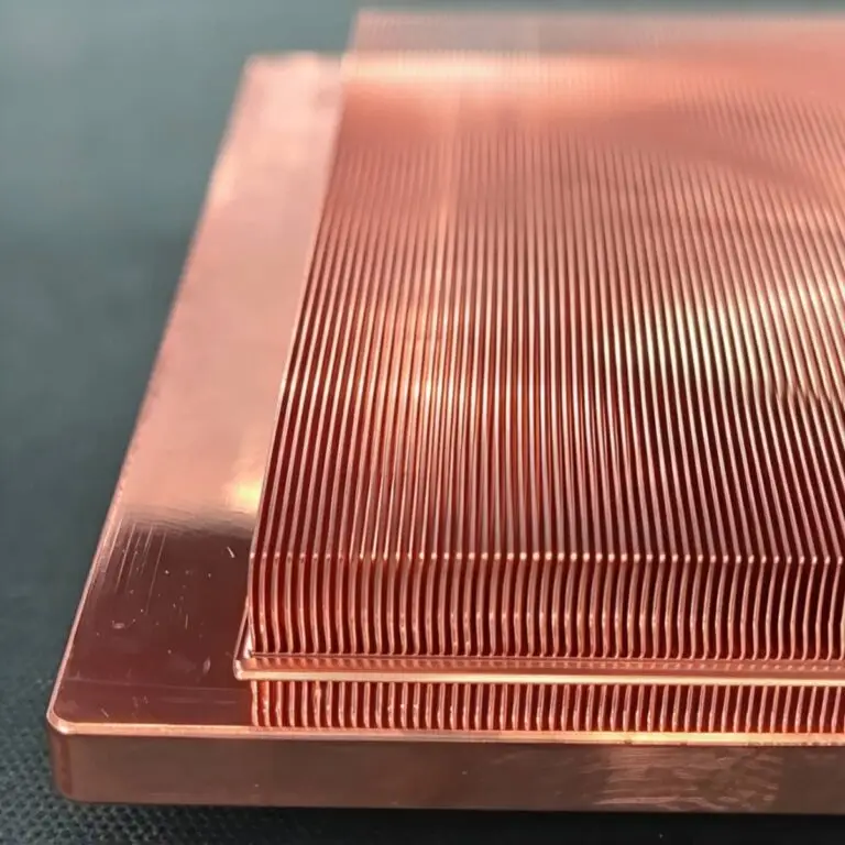
Diamond-Copper Thermally Conductive Composite. High thermal conductivity, tunable CTE, robust.

The DE-CW-1310 DFB EPI wafer, a high-performance epitaxial structure designed for distributed feedback (DFB) lasers operating at 1310 nm....

Ceramic thin-filmvacuum sensor Optical gas massflowmeter Liquid mass flowmeter Force sensor MEMS...

Photoelectric sensing chip Light source chips Optical transmission and modulationchips Optical detection and receptionchips...

Using a“Detach Core”which has two-layers carrier foil structure on the surface as a core, and forming...

Tenting process is a kind of subtractive process, the process as follows: Laminating photosensitive film...

Modified Semi-Added Process abbreviated as mSAP, which can be used on the core or build-up layers, pattern...
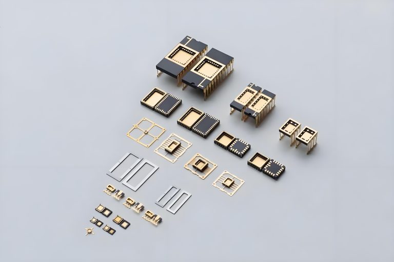
Semi-Added Process abbreviated as SAP, using on the build-up-layer pattern forming as follow:First depositing...
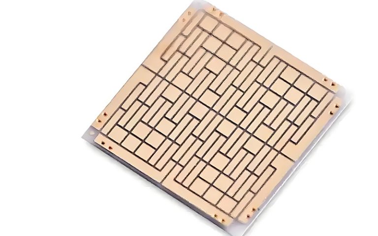
The product generally adopts the pressing lamination process of semi-curing sheets , and line formation...
The products generally adopt the Build-up Film Lamination process, and the circuit formation uses the...