
Wafer backgrinding is the step that thins a processed wafer for 3D integration, power management and mechanical fit. Done well, it is a quiet part of the line. Done poorly, it is where a wafer that passed electrical test loses usable dies: warpage that the next process cannot handle, chipping at the edge, and thickness variation (TTV) that the device does not tolerate.
This article treats backgrinding as a control problem, not a machine setting: what the grinding, lapping and polishing sequence can do, how the parameters interact with the wafer’s state, and where the inspection has to sit so that the three failure modes stay bounded through dicing and assembly.

Thinning is a sequence, and each stage earns its place. The wafer is bonded to a carrier (tape or vacuum), ground down in steps from coarse to fine grit to remove the bulk of the thickness, then lapped and polished to the final surface. The grind does the material removal, the lap and polish do the surface and the final flatness. The split matters because a wafer that is ground to its final thickness in one aggressive pass carries more stress into the surface than one that is brought to final dimension in a fine step.
The DEEPETCH wafer thinning device page is the equipment reference for this stage, and the wafer polishing equipment page covers the surface-finishing half of the sequence. On the line, the two are one process even though they are two machines: the backgrinding recipe includes the lapping and polishing steps that follow it.
A thinned wafer warps because the frontside film stack and the grinding itself leave stresses in the silicon. Thinning releases some of that stress; the grind adds some more. As the wafer gets thinner, it has less stiffness to hold a flat shape, which is why the warpage budget gets tighter exactly when the process is least forgiving. The variables are down force, spindle speed, the grit sequence, cooling, and the mounting method: a wafer with bow on entry warps differently from a flat one, and a tape-mounted wafer carries a different clamping load than a vacuum one.
The practical read: warpage is set by the wafer state plus the recipe, and the recipe’s job is to add as little new stress as possible while removing material. That is why the final steps are light passes rather than a single heavy cut, and why the bow measured on the incoming wafer belongs in the grinding recipe sheet, not in a separate memo.

Edge chipping is a local event, and its causes are local: the state of the mounting interface at the edge, the last grit in the sequence, debris at the rim, and the handling after the wafer leaves the machine. A wafer that is clean and flat in the die area can still carry chips at the edge, and the chips are exactly where the next process, dicing, is looking. The wafer dicing article covers what the street must protect after thinning; the backgrinding side of that contract is a clean edge and a surface the blade does not dig into.
The controls are unglamorous and specific: a grit sequence that ends fine, cooling that does not thermal-shock the edge, a mounting interface free of particles at the rim, and a handling step that keeps the backside clean from the moment the wafer is released.
TTV is the in-plane variation of thickness, and it is the number the downstream processes read. The grind head and table geometry, the down-force consistency and the wafer’s own bow all contribute, and a flat 500 um wafer has a different TTV problem from a 50 um one. The point to fix before the first pass is how TTV is measured: how many points, across what pattern, and against what limit, because a wafer backgrinding spec with a TTV limit but no measurement plan is a hope, not a specification.
Inspection is where the three modes get bounded. TTV is read at multiple points after the final step; warpage is read by metrology at the same points; chipping is read optically or by SEM at the edge, on a sample or 100 percent depending on the application. A wafer backgrinding line without these reads is grinding to a guess, and the probe station and AOI line covers the test and inspection stations where the reads happen, while the automatic dicing saw is where the thinned wafer goes next.
A thinning trial is only as good as the inputs it is given. Send the incoming state (material, diameter, bow, flatness, backside condition), the target thickness and TTV limit, the bow and warp limit, the chipping acceptance per region, the mounting method, and the downstream process the wafer goes to. With those, the trial output is a recipe you can scale: a parameter set with the failure modes bounded, not a set of machine numbers that happened to work on one wafer.
DEEPETCH carries the equipment on both sides of this step, from the wafer thinning device to the wafer polishing equipment and the automatic dicing saw that follows. Send DEEPETCH the incoming wafer state, the target thickness and the acceptance drawing with the open items marked, and the recipe you get back is one you can hold in production.
A No. The frontside film stack sets the baseline stress, and the wafer’s incoming bow sets the starting shape. Backgrinding can only add or remove a bounded amount of stress; the recipe is tuned to add as little as possible.
A No. The limit depends on what the die area tolerates and what the street is allowed to carry. An edge chip in the street is a different acceptance question from a chip on a die face, and the TTV limit follows the device, not the wafer.
A No. Laser-assisted thinning removes material without mechanical contact, which helps where the wafer is too fragile for a grinding head. It is a different process with its own surface and edge behavior, and the choice is made on the wafer state and the downstream requirement, not on a default.
Report the parameter set with the three bounded numbers: TTV at the measured points, warpage at the same points, and chipping per region against the acceptance drawing, with the incoming wafer state recorded next to them so the result is repeatable.
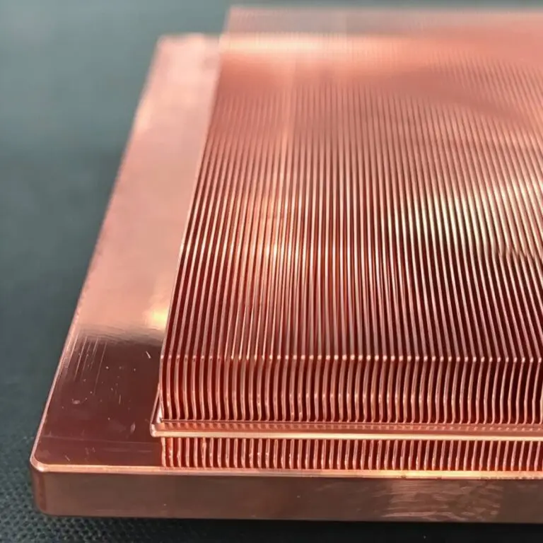
Diamond-Copper Thermally Conductive Composite. High thermal conductivity, tunable CTE, robust.

The DE-CW-1310 DFB EPI wafer, a high-performance epitaxial structure designed for distributed feedback (DFB) lasers operating at 1310 nm....

Ceramic thin-filmvacuum sensor Optical gas massflowmeter Liquid mass flowmeter Force sensor MEMS...

Photoelectric sensing chip Light source chips Optical transmission and modulationchips Optical detection and receptionchips...

Using a“Detach Core”which has two-layers carrier foil structure on the surface as a core, and forming...

Tenting process is a kind of subtractive process, the process as follows: Laminating photosensitive film...

Modified Semi-Added Process abbreviated as mSAP, which can be used on the core or build-up layers, pattern...
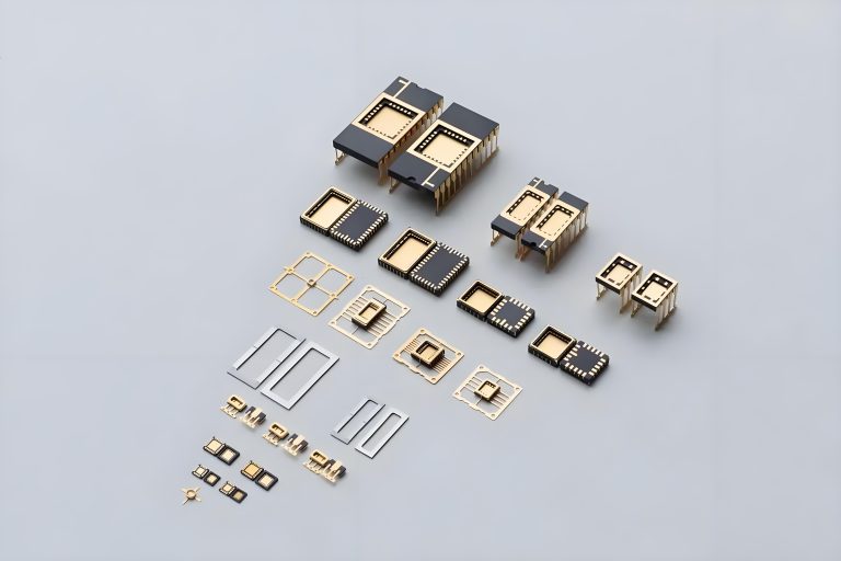
Semi-Added Process abbreviated as SAP, using on the build-up-layer pattern forming as follow:First depositing...
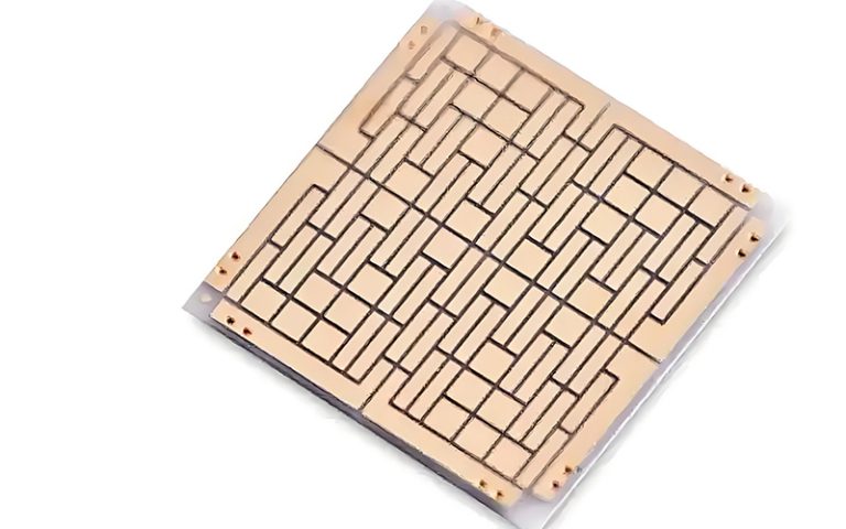
The product generally adopts the pressing lamination process of semi-curing sheets , and line formation...
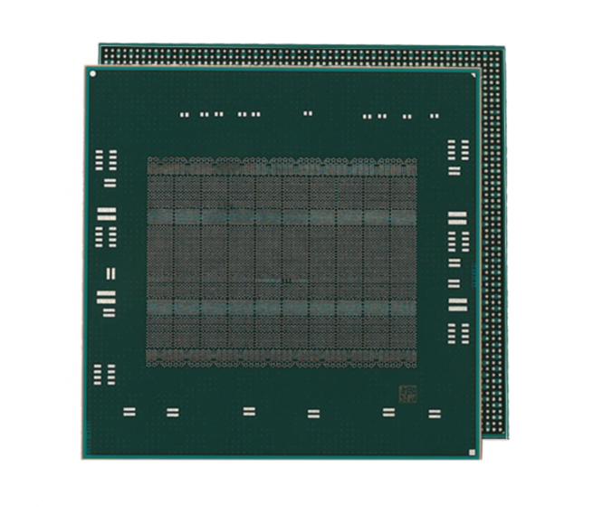
The products generally adopt the Build-up Film Lamination process, and the circuit formation uses the...