
A Fiber Patch Cable should not be selected by cable color or connector shape alone. At 400G, a cable may fit the port mechanically yet fail because its fiber mode, channel count, polarity, wavelength, or optical loss does not match the transceiver.
DEEPETCH supplies high-speed optical modules and related data communication solutions for data centers, AI computing facilities, cloud systems, and supercomputing environments. Its QSFP-DD 400G product range provides a useful selection reference. The QSFPDD-400G-SR8, QSFPDD-400G-DR4, and QSFPDD-400G-FR4 all support 400Gbps, but they use different optical connectors, wavelengths, fiber architectures, and transmission distances. These differences show why cable selection must begin with the exact module specification.

The correct fiber patch cable belongs to a complete optical channel. The transceiver, patch cord, trunk cable, adapters, patch panels, and receiving port must follow the same optical design. A mismatch at any point can prevent link establishment or leave too little margin for stable operation.
A multimode patch cord is commonly used for compact routes inside data halls and equipment rooms. DEEPETCH’s QSFPDD-400G-SR8 operates at 850nm, uses VCSEL + PIN components, and has an MPO-16/APC optical interface. Its listed reach is 60 meters over OM3 or 100 meters over OM4.
This configuration fits connections between nearby switches, racks, and rows. The OM3 vs OM4 fiber decision should be based on the complete routed distance rather than the straight-line distance between cabinets. Vertical drops, patch panels, cable managers, and service loops all add length.
Buyers must also verify whether the installed trunk supports the required fiber count and polarity. Writing only “400G multimode MPO cable” in a purchase order does not provide enough information.
A single-mode patch cord becomes more practical when the route exceeds short multimode limits or when the network may expand beyond the current room.
DEEPETCH’s QSFPDD-400G-DR4 operates at 1310nm, uses an MPO-12/APC connector, and supports a listed distance of 500 meters. The QSFPDD-400G-FR4 uses four wavelengths, a Duplex LC connector, and a listed reach of 2 kilometers.
These models represent two different single-mode architectures. DR4 uses parallel single-mode fibers and suits longer routes across large data halls or buildings. FR4 carries several optical wavelengths through LC duplex single-mode cabling, making it relevant for routes where an existing two-fiber infrastructure must be retained.
Single-mode provides more distance, but it is not automatically necessary for a short fixed connection. The choice should reflect actual layout and expansion requirements.
The maximum distance printed on a module specification does not guarantee that every route within that distance will work. A 400G optical link budget must account for all sources of attenuation.
A practical calculation follows this structure:
Available Optical Budget − Total Channel Loss = Remaining Operating Margin
The available budget comes from the difference between the transceiver’s minimum transmit power and receiver sensitivity. Total channel loss may include:
Two routes of equal length can produce different results. A direct cable with two connections may retain more margin than a shorter route passing through several panels and adapters.
DEEPETCH lists MPO-16/APC for QSFPDD-400G-SR8 and MPO-12/APC for QSFPDD-400G-DR4. The patch cord, adapter, and inspection process must follow the specified interface. An APC connector should not be mated with an incompatible polish. Dust, oil, scratches, and incomplete mating can also consume optical margin.
Before commissioning, inspect both ends, clean them when necessary, and record every connection point in the link-loss worksheet.
A fiber patch cable should be selected after the route has been measured and the port map has been confirmed. Distance is one filter, but cabinet density, patch-panel count, installed trunks, and future moves can change the final decision.
For short 400G links, QSFPDD-400G-SR8 is the most relevant DEEPETCH reference. It can be paired with the specified MPO-16/APC multimode infrastructure when the complete route remains within 60 meters over OM3 or 100 meters over OM4.
This arrangement suits nearby racks and short row-to-row links. Before ordering, confirm:
MPO polarity management should be documented in the project drawings. Otherwise, installers may receive components that are individually correct but cannot form a valid end-to-end channel.
For links between separate equipment rooms, floors, or distant rows, QSFPDD-400G-DR4 supports a 500-meter single-mode route through MPO-12/APC.
The purchase specification should state the module model, fiber mode, connector, polish, polarity, route structure, and acceptance method. This prevents a substitute from being approved only because it supports 400Gbps.
The optical budget should also be recalculated if extra patch panels or adapters are added during installation.
QSFPDD-400G-FR4 is more suitable for facility or campus routes that require up to 2 kilometers. It uses a Duplex LC interface and four listed wavelengths of 1271, 1291, 1311, and 1331nm.
This design can fit projects that already have duplex single-mode cabling. It may also reduce the required fiber count compared with a parallel optical route.
However, selecting FR4 for two nearby cabinets simply because it has more reach may create unnecessary changes to the transceiver, cabling, and spare-parts plan.
To match a fiber patch cable, read the transceiver specification in a fixed order: form factor, data rate, optical type, wavelength, connector, fiber mode, reach, and operating environment.
| DEEPETCH Product | Fiber Type | Connector | Wavelength | Listed Reach | Suitable Use |
|---|---|---|---|---|---|
| QSFPDD-400G-SR8 | Multimode | MPO-16/APC | 850nm | 60m OM3 / 100m OM4 | Short data-hall links |
| QSFPDD-400G-DR4 | Single-mode | MPO-12/APC | 1310nm | 500m | Longer in-building links |
| QSFPDD-400G-FR4 | Single-mode | Duplex LC | 1271/1291/1311/1331nm | 2km | Facility or campus links |
The three modules have listed power consumption limits of 8W, 10W, and 11W respectively, with a case temperature range of 0°C to 70°C.
Choose QSFPDD-400G-SR8 when both ports support QSFP-DD, the route is short, and the installed infrastructure supports MPO-16/APC multimode transmission.
Do not replace the required assembly with an MPO-12 cable merely because both belong to the MPO connector family. Connector format, fiber count, and optical architecture must all match.
Choose QSFPDD-400G-DR4 when the route exceeds the listed SR8 range but remains within 500 meters.
Its MPO-12/APC interface also shows why MPO does not always indicate multimode transmission. Maintenance teams should store DR4 single-mode assemblies separately from multimode MPO stock.
Choose QSFPDD-400G-FR4 when the project needs up to 2 kilometers and uses Duplex LC single-mode infrastructure.
Every adapter and patch panel must follow the same fiber type and connector plan. FR4 is especially relevant when an existing two-fiber route needs to be retained during a 400G upgrade.
Most avoidable project delays come from incomplete interface information, uncoordinated delivery dates, uncontrolled substitutions, or poorly labeled spare stock. Module sourcing and cable purchasing should therefore follow one approved link BOM.
Before fixing the installation date, confirm that the selected transceivers, matching cables, adapters, and patch-panel components can arrive within the same project window.
DEEPETCH’s Chips In-stock sourcing service can support component availability checks for prototype, repair, and small-batch requirements. In a fiber-link project, this service should remain tied to the approved optical BOM rather than being treated as a separate chip-purchasing topic.
Any replacement must match the required form factor, wavelength, connector, reach, and interface. A component that only matches the nominal data rate may force changes elsewhere in the link.
Projects involving mixed port types, custom PCBA design, limited enclosure space, unusual routing, or nonstandard interfaces may need engineering review before production.
The IDM Customization Process is relevant when optical modules, electronic assemblies, mechanical structures, and cabling must be evaluated together. Buyers should provide the network topology, connector map, route restrictions, operating environment, quantity, and acceptance requirements.
Prototype validation should check physical fit, link operation, thermal conditions, and repeatable assembly before the production BOM is frozen.
Inspect connector end faces before mating. Keep protective caps on unused ends, avoid touching ferrules, control cable bends, and label both ends according to the port map.
Replacement stock should be separated by:
A label such as “400G fiber patch cable” is too broad for maintenance work.
Use the transceiver specification to narrow the available cable types, then verify the physical route and optical margin. The selected link should remain serviceable during installation, testing, replacement, and later expansion.
Choose multimode when the measured route stays within the SR8 limit and the network supports MPO-16/APC parallel cabling. QSFPDD-400G-SR8 is the relevant DEEPETCH reference for short 400G data-hall links.
Choose single-mode when the route exceeds multimode reach or future relocation is likely. QSFPDD-400G-DR4 suits a 500-meter MPO-12/APC route, while QSFPDD-400G-FR4 suits a 2-kilometer Duplex LC route.
Before approving the order, complete this final checklist:
Before releasing a fiber patch cable order, prepare the port map, module models, routed length, connector plan, polarity, patch-panel count, operating conditions, quantity, and delivery schedule. For unresolved optical matching, component availability, or custom integration requirements, contact DEEPETCH with the planned topology and BOM.
Q: How Do I Calculate the Loss Budget for a Fiber Patch Cable Link?
A: Start with the available optical budget from the exact transceiver specification. Subtract fiber attenuation, connector losses, splices, patch panels, adapters, and an engineering margin. The remaining margin must be sufficient for the required operating conditions.
Q: Can an MPO Cable Be Used for Both Single-Mode and Multimode 400G Links?
A: Yes, but they require different assemblies. DEEPETCH’s QSFPDD-400G-SR8 lists MPO-16/APC for multimode, while QSFPDD-400G-DR4 lists MPO-12/APC for single-mode. Fiber type, count, polish, and polarity must match.
Q: Is Single-Mode Always Better for a Network Upgrade?
A: No. Single-mode offers more reach, but a short fixed route may remain simpler with multimode. Compare installed cabling, total link loss, connector changes, replacement stock, and future route plans before deciding.

The DE-CW-1310 DFB EPI wafer, a high-performance epitaxial structure designed for distributed feedback (DFB) lasers operating at 1310 nm....

Ceramic thin-filmvacuum sensor Optical gas massflowmeter Liquid mass flowmeter Force sensor MEMS...

Photoelectric sensing chip Light source chips Optical transmission and modulationchips Optical detection and receptionchips...

Using a“Detach Core”which has two-layers carrier foil structure on the surface as a core, and forming...

Tenting process is a kind of subtractive process, the process as follows: Laminating photosensitive film...

Modified Semi-Added Process abbreviated as mSAP, which can be used on the core or build-up layers, pattern...
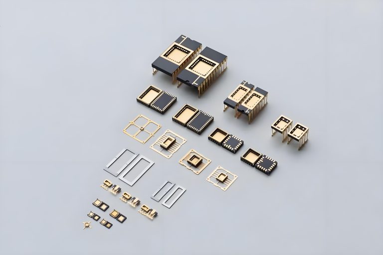
Semi-Added Process abbreviated as SAP, using on the build-up-layer pattern forming as follow:First depositing...
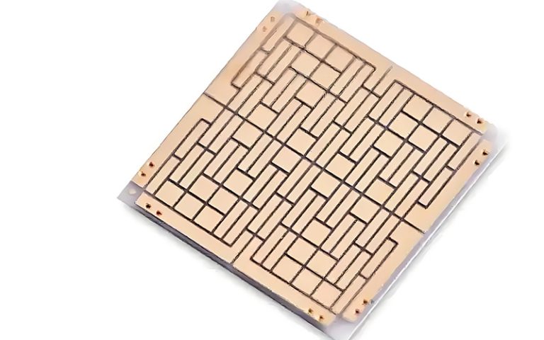
The product generally adopts the pressing lamination process of semi-curing sheets , and line formation...
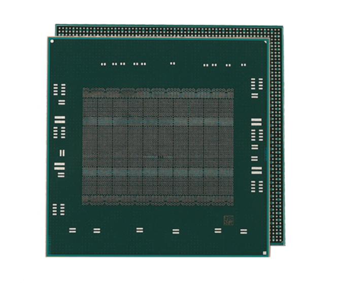
The products generally adopt the Build-up Film Lamination process, and the circuit formation uses the...
Equipment features: 1. Non-destructive precision testing Micrometer-level probe contact technology...