
A PCBA may pass inspection yet fail after heat, load, vibration, or repeated power cycling exposes a hidden weakness. In-Chip Monitoring adds operating data from inside the device, allowing engineers to detect abnormal temperature, voltage, current, timing, or status changes before the fault becomes permanent. It does not replace production inspection; it adds evidence for faults that appear only under real operating conditions.
DEEPETCH works across semiconductor design, sensor development, packaging, testing, and customized electronic manufacturing. For monitoring-enabled PCBAs, the task is to match sensing, interfaces, calibration, firmware thresholds, packaging, and production tests to the failure mode. This approach is especially useful in aerospace circuits, satellite communication electronics, 6G hardware, and UAV control systems, where field repair is difficult.

Conventional inspection can find many assembly defects, but it cannot always show what happens inside an IC during a transient load or slow thermal drift. A useful plan links internal data with board-level measurements and manufacturing records.
Embedded chip telemetry can reveal rising internal temperature, repeated undervoltage, abnormal current, or timing warnings while the board still works. For custom PCBA reliability monitoring, each value needs a normal range, fault level, sampling method, and defined response.
AOI checks visible assembly conditions. X-ray inspection can reveal hidden solder or package-interconnect defects. ICT and functional testing check electrical behavior at defined test points. In-chip monitoring records internal or local conditions during startup, stress testing, normal use, or a fault.
Prototype data can guide component placement, heat spreading, power-rail design, firmware limits, and test coverage. Pilot-build and field data can show whether variation is acceptable and whether a weakness is repeatable. This feedback supports revisions to the BOM, layout rules, inspection points, or test sequence.
Start with conditions that can stop the system, damage costly components, or create a safety risk. Monitoring every parameter adds board space, firmware work, and validation cost. Selective coverage is usually more useful.
Temperature monitoring in PCBA design should focus on processors, FPGAs, regulators, RF amplifiers, motor drivers, and dense connector areas. One ambient reading may miss a local hotspot.
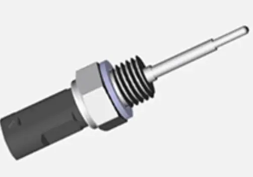
The DEEPETCH Customizable sensor series includes NTC, PT platinum-resistance, and thermocouple options. Its documented temperature range extends from -80°C to 2350°C, while range, output, and structure can be selected for the application. Choose the actual operating window rather than the widest range.
Current monitoring for power integrity is useful on battery inputs, regulated rails, motor-drive paths, RF power stages, and processing sections with changing loads. An unusual pattern may indicate overload, a partial short, unstable bias, degradation, or incorrect firmware behavior.
DEEPETCH documents a current sensor with 8–16 V operating voltage, -40°C to 85°C operating temperature, customizable current range and accuracy, and analog or digital output. Specifications should also define continuous and transient current, fault level, bandwidth, isolation, and allowable voltage drop.
Connectors may loosen, heavy parts may strain solder joints, and PCB flexing can create intermittent contact. DEEPETCH vibration-sensor data includes 4–20 mA True RMS output, IP67 protection, 5–1000 Hz frequency response, -40°C to 250°C operation, and a 1000g peak shock limit. These specifications suit harsh-environment assemblies.
| Failure Concern | Primary Measurement | Main Selection Point |
|---|---|---|
| Local overheating | Internal temperature plus external sensor | Range, location, response time |
| Abnormal loading | Current and voltage | Range, bandwidth, isolation, output |
| Mechanical fatigue | Vibration and shock | Frequency range, mounting, protection |
| Intermittent fault | Event logs and embedded telemetry | Timestamp, threshold, data access |
A purchase specification should describe the failure to detect and the action required after detection. Listing only a sensor type leaves key decisions unresolved.
State whether the project must detect overheating, overcurrent, unstable power, shock, vibration, drift, or progressive degradation. Rank risks by safety impact, mission interruption, component cost, and repair difficulty. A satellite board may prioritize thermal drift and power stability, while a UAV power board may prioritize current surges and vibration.
Specify normal and fault ranges, accuracy, response time, sampling rate, output format, alarm threshold, board space, and power budget. Include isolation, grounding, and noise-control requirements near high-current or RF circuits. The selected range needs practical headroom without reducing the useful signal below the required resolution.
The measurement path includes the sensor, analog front end, ADC, firmware conversion, threshold logic, and interface. Any stage can introduce offset, drift, delay, or scaling error.
DEEPETCH’s documented capabilities include temperature and humidity compensation, characteristic calibration, linearization, mass-production calibration, packaging and product testing, laboratory support, failure analysis, and customer application support. These steps help convert prototype limits into repeatable production controls.
For purchasing teams, the final decision should depend on whether the monitoring function can change a real engineering or maintenance outcome. Use in-chip monitoring when faults are load-dependent, intermittent, difficult to reproduce, or costly to diagnose after deployment. Use external board-level sensors when the critical condition occurs around the IC, such as power-path current, connector vibration, or localized heat near a regulator. Use both methods for aerospace, satellite, 6G, and UAV assemblies where internal status and environmental stress must be correlated. If a fault can already be detected reliably during functional testing and the board remains easy to access, additional monitoring may not justify the extra BOM cost, PCB space, firmware work, calibration, and validation effort. Buyers should therefore compare detection value against implementation and lifecycle cost rather than selecting the largest possible set of monitored parameters
The strongest use cases involve harsh conditions, long service periods, or limited maintenance access. Carefully selected data can shorten fault isolation.
Aerospace PCBA reliability depends on temperature cycling, power transients, mechanical stress, and long operating periods. Internal status data can show where the device lost margin, while temperature, current, or vibration sensing identifies the external condition. Buyers should define log storage, timestamps, reset behavior, and post-fault access.
Dense RF and digital integration creates local heat and changing power demand. During prototype testing, in-chip monitoring can show how internal status changes with output power, processing load, or temperature. External current and temperature channels provide a board-level reference. Monitoring does not correct poor grounding, weak shielding, impedance errors, or unstable bias, but it helps locate when those weaknesses appear.
A UAV may combine flight control, processing, navigation, communication, battery management, and motor drive in limited space. For UAV flight control PCBA monitoring, a practical set includes controller status, local temperature near processing and power devices, current sensing on critical rails, and vibration data. Selection should follow the failure that must be detected before control, communication, or power is lost.
Monitoring affects the schematic, layout, firmware, enclosure, calibration fixture, and production records. Late addition often creates routing conflicts or incomplete validation.
Through its IDM Customization Process, DEEPETCH can align sensing requirements with circuit design, packaging, prototypes, and functional, performance, and reliability testing. Buyers should provide operating conditions, target measurements, thresholds, interfaces, board-space limits, and expected quantity. Prototype tests should cover startup, shutdown, normal load, maximum load, and controlled faults.
The production plan should include incoming checks, calibration status, firmware version, test limits, traceability, and finished-unit verification. A threshold copied from one prototype is not automatically suitable for volume production. Limits must account for component tolerance, sensor variation, thermal-path differences, measurement error, and operating margin.
A common procurement mistake is approving the sensor part number while leaving the complete measurement chain uncontrolled. The same sensor can produce different results after changes to its PCB position, surrounding copper area, mounting method, airflow, analog front end, ADC reference, firmware conversion formula, or calibration process. Another risk is copying an alarm threshold directly from a component datasheet or a single prototype. That limit may create false alarms in production or fail to detect a genuine abnormal condition. Before releasing the design, buyers should ask the EMS supplier to freeze the sensor location, signal-conditioning circuit, firmware version, calibration reference, test method, and acceptance limits. A controlled reference unit and traceable calibration records are also useful when production moves between prototype, pilot build, and repeat orders. Any later substitution or layout change should trigger a documented review rather than being treated as a routine BOM update.
After shipment, fault records should return to design review and failure analysis. The service process should define data collection, log access, return-analysis triggers, and change control.
Reliable manufacturing comes from connecting in-chip monitoring with a clear failure model, suitable sensors, calibrated signal paths, and controlled production tests. The plan should be simple enough to validate and specific enough to support a decision.
Prepare the schematic or block diagram, operating environment, expected ranges, interface preference, alarm logic, validation requirements, and production forecast before supplier discussion. You can contact DEEPETCH to review which measurements belong inside the chip, which need external sensors, and how they should be tested during production.
Q: Does in-chip monitoring replace AOI, X-ray, ICT, or functional testing?
A: No. It records internal operating conditions or fault events. Production inspection and board testing still find assembly, soldering, interconnect, and functional defects. A reliable process uses both.
Q: Which sensor should be added first to a custom PCBA?
A: Start with the failure mode. Temperature sensing fits processors, regulators, RF amplifiers, and motor drivers. Current sensing fits critical power paths. Vibration sensing is more relevant to UAV, aerospace, satellite, mobile, and industrial equipment.
Q: What information does an EMS supplier need for In-Chip Monitoring integration?
A: Provide the target failure, normal and fault ranges, required accuracy, response time, interface, board-space limit, environmental conditions, alarm action, test method, traceability needs, and expected production volume.

The DE-CW-1310 DFB EPI wafer, a high-performance epitaxial structure designed for distributed feedback (DFB) lasers operating at 1310 nm....

Ceramic thin-filmvacuum sensor Optical gas massflowmeter Liquid mass flowmeter Force sensor MEMS...

Photoelectric sensing chip Light source chips Optical transmission and modulationchips Optical detection and receptionchips...

Using a“Detach Core”which has two-layers carrier foil structure on the surface as a core, and forming...

Tenting process is a kind of subtractive process, the process as follows: Laminating photosensitive film...

Modified Semi-Added Process abbreviated as mSAP, which can be used on the core or build-up layers, pattern...
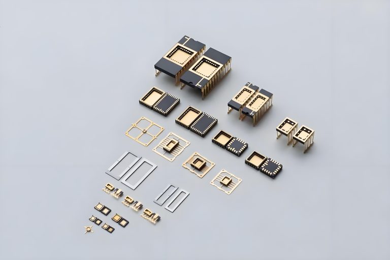
Semi-Added Process abbreviated as SAP, using on the build-up-layer pattern forming as follow:First depositing...
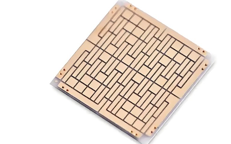
The product generally adopts the pressing lamination process of semi-curing sheets , and line formation...
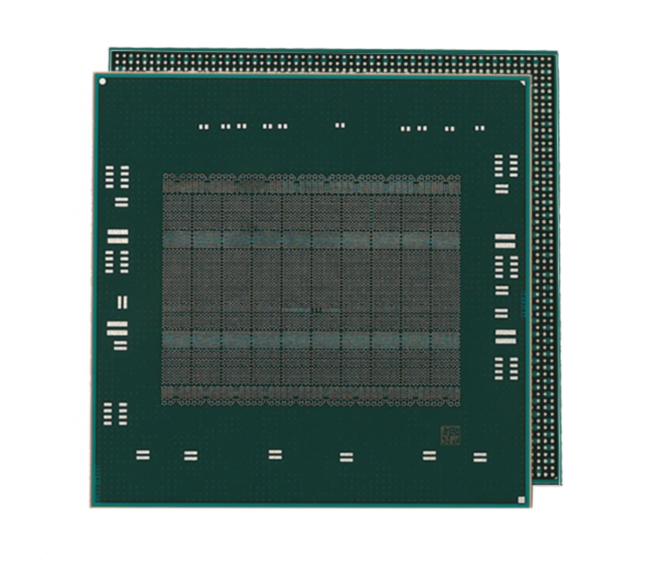
The products generally adopt the Build-up Film Lamination process, and the circuit formation uses the...
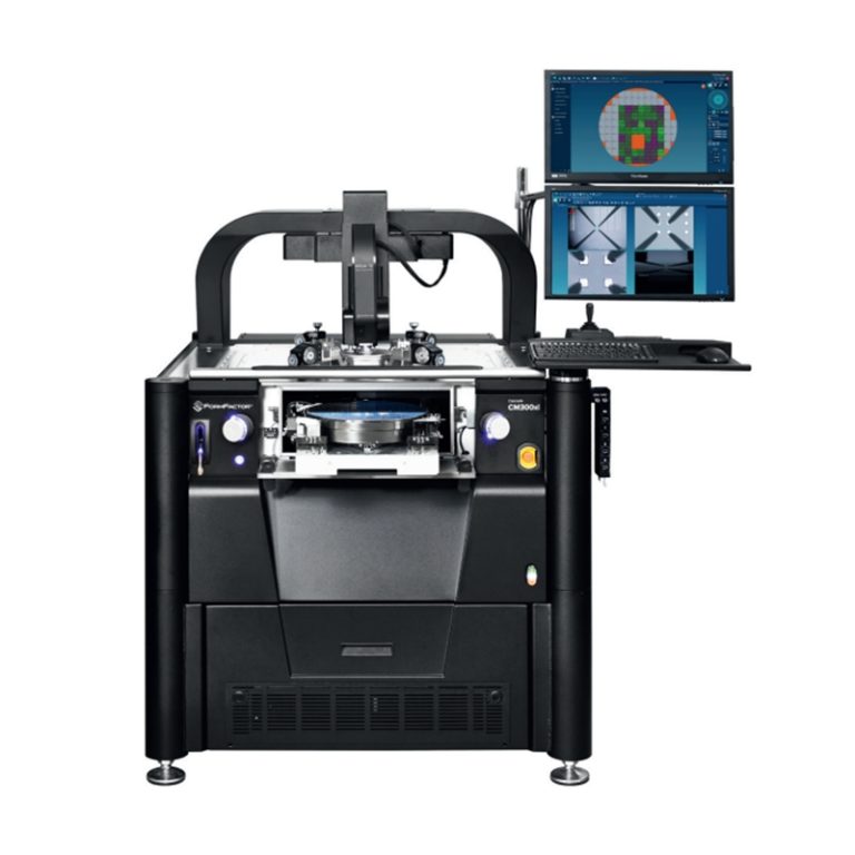
Equipment features: 1. Non-destructive precision testing Micrometer-level probe contact technology...